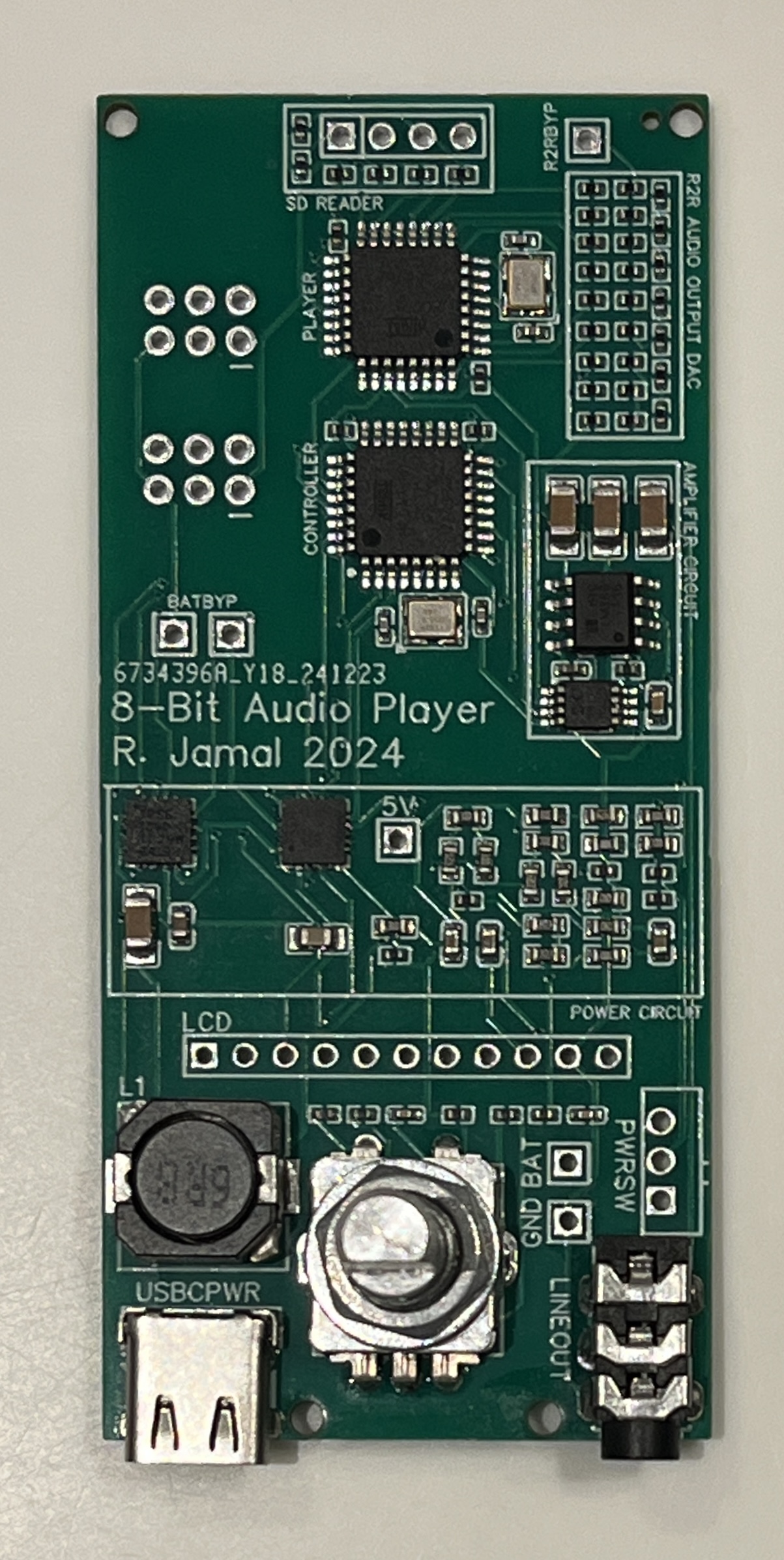
The 8-Bit Audio
Player makes use of an R/2R ladder and 8-bit, 16
KHz WAV files. In this
configuration, an ATmega328P reads audio samples
from an SD card, and sequentially outputs the
samples onto the R/2R ladder at a rate of 16 KHz.
The raw signal from the
output of the R/2R DAC is filtered through a
capacitor in a low-pass filter configuration.
It is then amplified through an LM386
audio amplifier, before finally being sent to
headphones through a 3.5 mm audio jack.
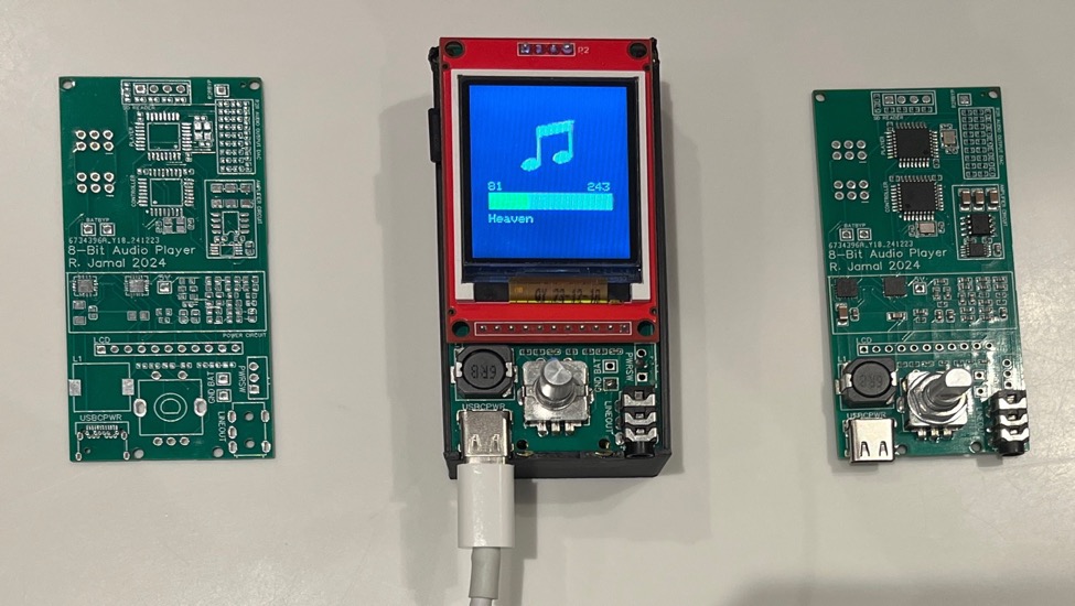
Custom PCBs showing assembly steps and enclosure (middle)
Digital-to-Analog Conversion
The basic concept of 8-Bit R/2R Audio Player comes from the R/2R DAC itself. An R/2R ladder,
or DAC, is a simple digital-to-analog converter (DAC) that converts an 8-bit, discrete value, to an analog
voltage between 0 and the
supply voltage using the principle of voltage division. It generally includes 8 switches that can either be turned on or
off, for a total of 2^8=256 steps between 0 and 5V. By connecting the 8 switch inputs to a microcontroller, a
stored 8-bit digital value can be converted to an analog voltage. In this configuration, the R/2R DAC
enables the microcontroller to emulate PWM with true analog voltage, instead of a duty cycle-based
approximation.
R/2R ladder DAC (Top Left Box)
GUI and User Input
The 8-Bit Audio Player has 2 microcontrollers used: one “slave” to read from the SD card and update the DAC, and
a master to coordinate which song to play, and by responding to user input through a rotary encoder and
to control a TFT screen with the song progress and a list of songs. To communicate between MCUs, I2C
is utilized. When the master wants to receive any information from the slave, it must send a request. Due
to certain limitations of the I2C protocol, when any request is sent, the same request routine must run. A
request routine is a function run when an I2C request is received. This means that the same data point is
sent for every request, in a standard configuration. The request routine is simply a function. It is not,
strictly speaking, an ISR. This means that many blocks of code can be efficiently run within the request
routine, and blocking calls are considered acceptable.
To request multiple data points, a command code
system is implemented. In this configuration, the
master sends a code corresponding to a data point,
which is placed into a buffer. Then, the master
sends a request. Within the request routine, a
subroutine is included for each point
The master MCU only has direct access to the display, the rotary encoder, and the I2C bus. Since it does
not have access to the SD card, it cannot directly read the song names to put on the display. To read the
song names, it requests the data from the player MCU. To do this, it first sends a value of 2, to place in
the code buffer. Then, it requests 32 bytes from the player, which reads the SD card, parses
it into a character array buffer, and sends 1 character (byte) at a time to the master which reconstructs the
data and parses it into a 2D array of characters. Since the master can only hold a finite number of song
names in its 2 KB of memory, the player maintains a global index based on the last song sent. This means
that on the next song name request, the next song is automatically sent.
The master MCU also contains images in program memory for a now playing screen (see above)